
Ladder Diagram Symbols Photos
The Ladder Diagram's name is derived from its ladder-like appearance, with rungs symbolizing individual logic conditions and coils representing outputs. For engineers familiar with relay-based control systems, the Ladder Logic's graphical representation is both intuitive and reassuring. As control and automation engineers, our expertise in.
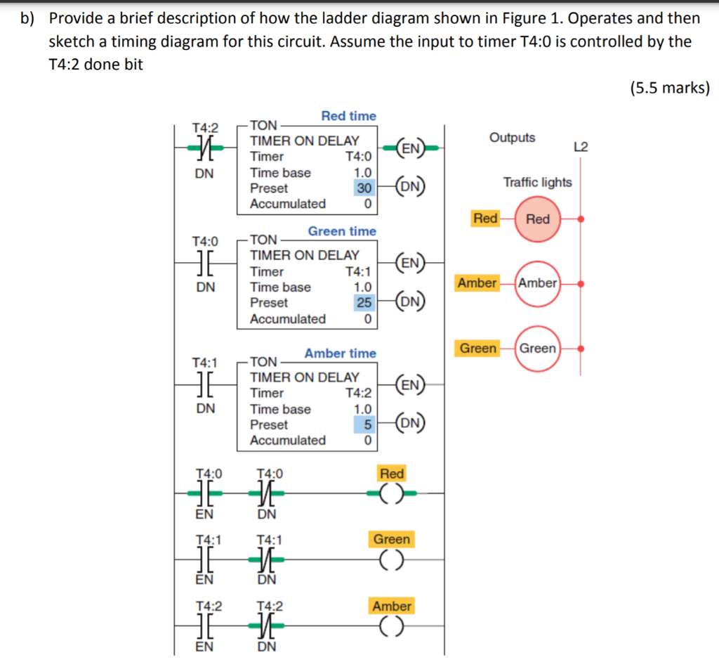
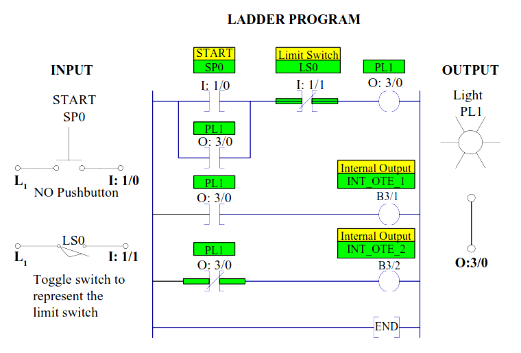
b) Provide a brief description of how the ladder diagram shown in Figure 1. Operates and then
ii Precautions for Safety Always read the specifications issued by the machine manufacturer, this manual, related manuals and attached documents before installation, operation, programming,
Ladder Logic Symbols All PLC Ladder Diagram Symbols LEKULE BLOG
1. What are Ladder Diagram Symbols. These are special Symbols that are commonly used in industrial control logic systems. As they resemble a ladder with two vertical supply power and as many horizontal lines that represent control units that's why they are called ladder diagrams. Ladder Diagram Symbols are the building blocks of ladder.

Motor Symbol In Ladder Diagram Wiring Diagram Schematica
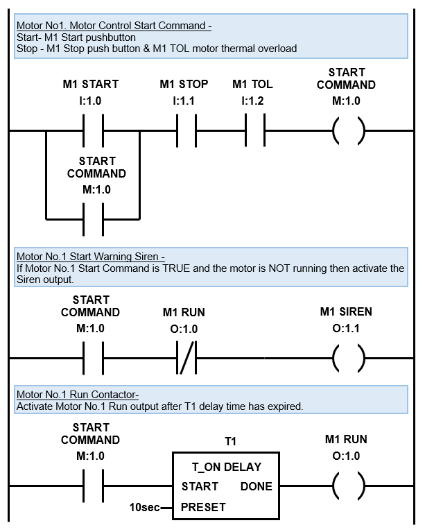
If the XIC is False, the PLC aborts this rung. Step 3 - The hypothetical current goes to the next instruction. Repeats Step 2 until the rung is completed. Step 4 - The PLC moves to the rung below. Ladder Logic PLC Programming XIC = OFF Example. In the example above, the XIC Instruction is tied to the bit "Condition1".
Ladder Logic Basics Ladder Logic World
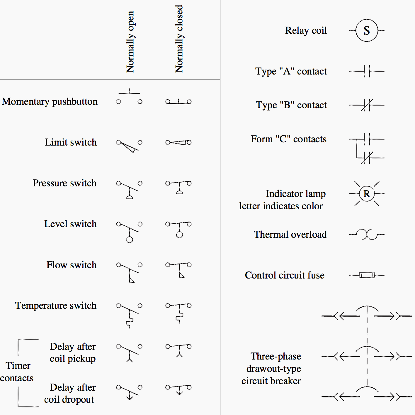
Instruksi Dasar Pemrograman Diagram Ladder. Simbol-simbol diagram ladder dan alamat memori digunakan untuk membuat program ladder. Beberapa simbol diagram ladder dasar mencakup Input (kontak NO), Input (kontak NC), dan Output. Simbol berbeda digunakan untuk merepresentasikan perangkat yang berbeda dalam diagram sirkuit rangkaian, tetapi dalam.
Ladder Logic Diagram Examples / Ladder Logic Basics Ladder Logic World / In the united states
Ladder logic symbols are the fundamental programming components used in ladder diagrams. In PLC programming, ladder logic symbols can be used individually or in combination to create logic instructions. Traditionally, ladder logic symbols were created for bit logic operations, but now include higher level functions such as timers, counters.
Ladder Diagrams Automation Community
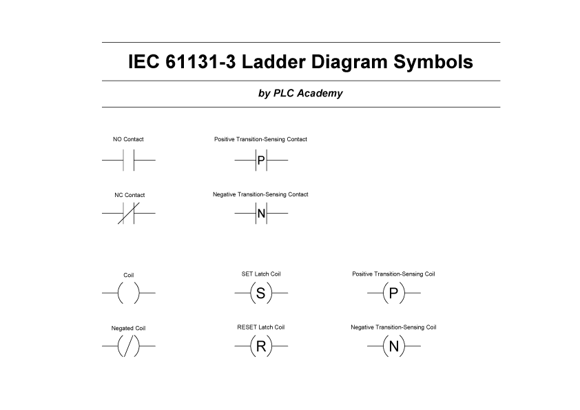
These symbols, when used according to the guidelines outlined in IEC 61131-3, allow for clear and standardized representation of control logic in ladder diagrams. Benefits of Referencing IEC 61131-3 Mentioning the specific standard for ladder logic symbols (IEC 61131-3) is beneficial for readers seeking more detailed information on the.
Ladder Diagram Symbols Photos
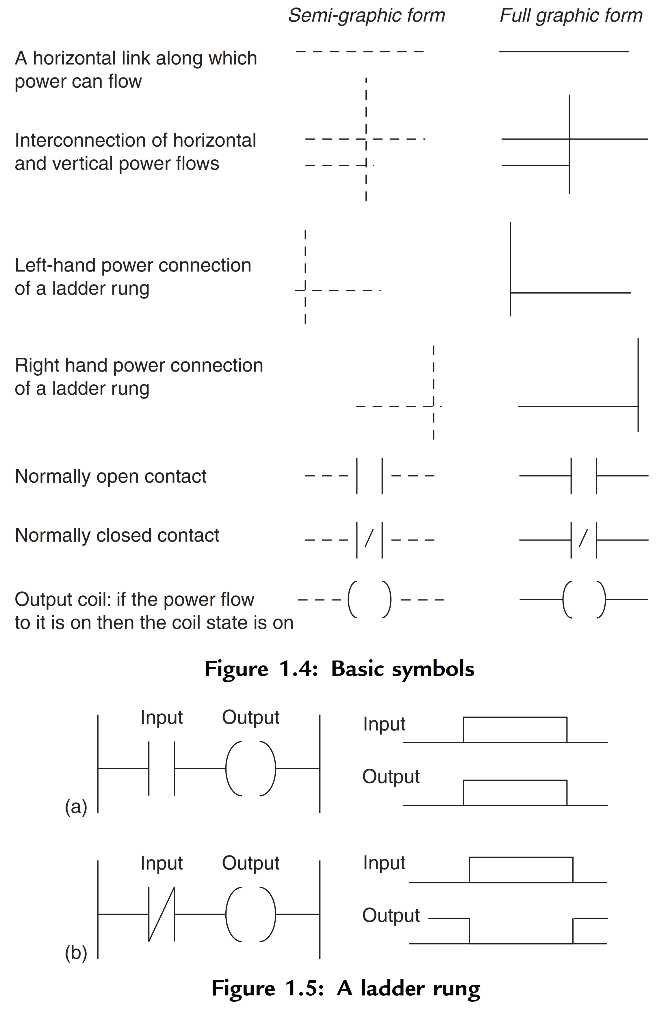
Ladder logic symbols represent various components and operations in a control system, such as inputs, outputs, logical operations, timers, counters, and more. Each symbol has a specific meaning and function in the ladder diagram. The standard ladder logic symbols are based on the electrical diagram symbols used in relay logic.
Introduction to PLC Ladder Diagrams Free PLC Tutorials Download
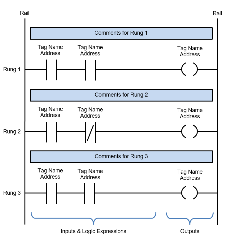
A ladder diagram is a type of schematic diagram used in industrial automation, describing circuits for logic control. Two vertical control rails and horizontal logic rungs make up the ladder diagrams to form what appears like a ladder. Tag ladder diagram symbols Share Report 5 2.4k. Add a comment. Post Recommended.

An example of ladder diagram Download Scientific Diagram
Pada Ladder diagram, bahasa pemrograman yang digunakan untuk membuat program untuk mengontrol sistem PLC disebut dengan 'Ladder Diagram Language' atau 'Ladder Logic Language'. Ini telah ditandai dengan representasi grafis, seperti kabel listrik untuk kontrol logika. Berbagai Simbol yang digunakan dalam Diagram Tangga:
Logic Ladder Diagram Examples / Examples Of Plc Ladder Logic Diagrams Ladder Logic Logic Plc
Ladder logic (also known as ladder diagram or LD) is a programming language used to program a PLC (Programmable Logic Controller). It is a graphical PLC programming language which expresses logic operations with symbolic notation. Ladder logic is made out of rungs of logic, forming what looks like a ladder - hence the name 'Ladder Logic'.
[DIAGRAM] Wiring Plc Ladder Diagram
PLC Basics. Ladder Logic Symbols - All PLC Ladder Diagram Symbols. by peter June 28, 2015. 10. Ladder logic symbols are the basic building blocks for ladder diagrams. Right here you will find all the ladder diagram symbols which are described in IEC 61131-3. The symbols are available for download in all formats and in a PDF-file.
Ladder Wiring Diagram Symbols / Ladder Logic Symbols Schematic Schematics Diagram Ladder
Figure (c) Ladder Diagram for the programming problem in Example above. The first three rungs S1, S2, and S3 are used for the control of the indicator lights and the power to the rest of the circuit. Momentary closure of switch 1PB will energize the contact relay 1CR; this in turn will close 1CR NO contacts and open 1CR NC contacts.

Ladder Wiring Diagram Symbols Bv 6044 Control Ladder Logic Diagrams Free Diagram Ladder
Ladder Logic Diagram Example 1 Computer Aided Manufacturing TECH 4/53350 27 Task: Draw a ladder diagram that will cause the output, pilot light PL2, to be on when selector switch SS2 is closed, push button PB4 is closed and limit switch LS3 is open. (Note: no I/O addresses yet.) Thought Process
Ladder Wiring Diagram Symbols / Ladder Logic Symbols Schematic Schematics Diagram Ladder
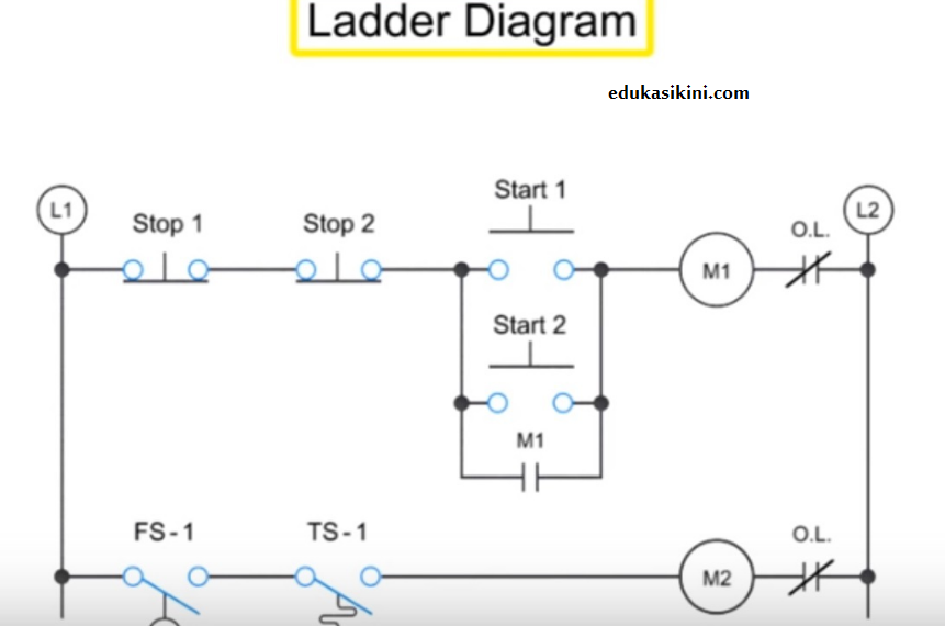
The example below shows a ladder diagram with pushbuttons (PB), control relays (CR), a motor (M) and a light (L). Similarities with Ladder Diagrams. Ladder logic was designed to have the same look and feel as electrical ladder diagrams, but with ladder logic, the physical contacts and coils are replaced with memory bits. Let's take a look.
Panduan ladder diagram Diagram logika Relay
It is called a ladder diagram because the program looks like a ladder with two vertical lines representing the power sources and horizontal lines representing the rungs. In a ladder diagram, there are various symbols used to represent different elements and functions. These symbols help programmers create logic for controlling and monitoring.