Inductor Symbols Solenoid, Chock and Coils Symbols
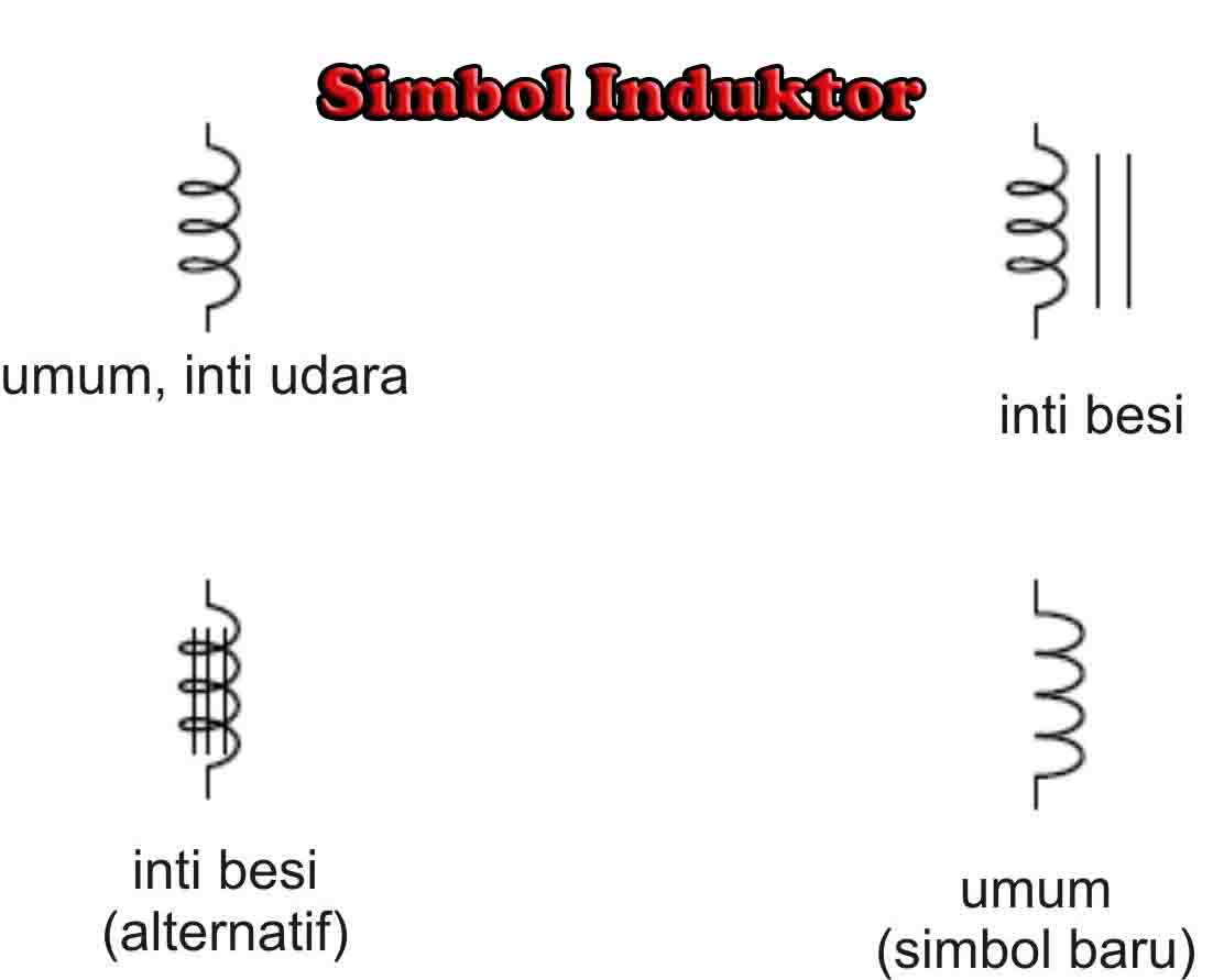
The schematic symbols for inductors are shown in Figure 9.2.10 . The standard symbol is at the top. The variable inductor symbol is in the middle and is a twolead device, somewhat reminiscent of the symbol for a rheostat. At the bottom is the symbol for an inductor with an iron, ferrite, or similar high permeability core.
FUNGSI, JENISJENIS DAN PENGERTIAN INDUKTOR SMKN1RENGASDENGLOK
Toroid. A very common type of inductor is the toroid, a small doughnut-shaped coil, as shown in figure 4. Fig.4: Toroid with Toroidal Winding. The coil may consist of a single-layer winding, a multilayer winding, or even several coils wound on the same toroid. The core is of ferrite material, which has a high permeability.

Symbol For Inductor ClipArt Best
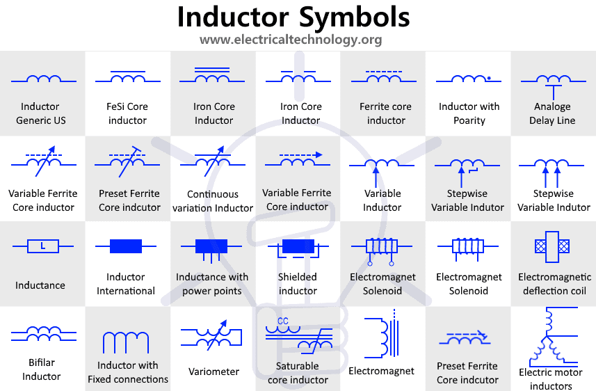
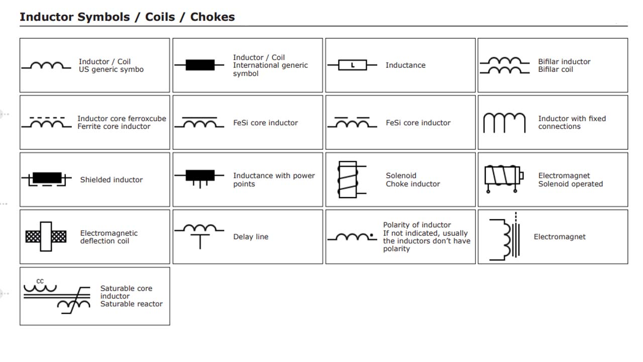
Inductor Symbols / Coils. The inductors or coils are electrical passive components that have a certain number of turns of wire that introduce magnetic inductance to an electrical circuit to produce a magnetic flux or to mechanically react to magnetic flux variations.
Symbol For Inductor ClipArt Best
An inductor, also called a coil, choke, or reactor, is a passive two-terminal electrical component that stores energy in a magnetic field when electric current flows through it. [1] An inductor typically consists of an insulated wire wound into a coil . When the current flowing through the coil changes, the time-varying magnetic field induces.

Understanding Inductors Principles, Working, and… CircuitBread
Electrical symbols & electronic circuit symbols of schematic diagram - resistor, capacitor, inductor, relay, switch, wire, ground, diode, LED, transistor, power.
Inductor Types and Symbols Electrical Academia
Electrical Symbols — Inductors. An inductor, also called a coil or reactor, is a passive two-terminal electrical component which resists changes in electric current passing through it. It consists of a conductor such as a wire, usually wound into a coil. Energy is stored in a magnetic field in the coil as long as current flows.

Electrical Schematic Symbol Inductor CAD Block And Typical Drawing
An inductor placed in series (in line) with a conductor, such as a wire or circuit board trace, blocks or impedes changes in current and functions as a low pass filter. Because inductors restrict or choke changes in current, they are also called "chokes". For example, a broadband (wideband) bias choke in line with the DC bias of an amplifier.

Inductors symbol CAD Block And Typical Drawing
An inductor is a passive electrical device ( typically a conducting coil) that introduces inductance into a electric circuit. It is basically a coil of wire with many winding, often wound around a core made of a magnetic material, like iron. Simplest form of an inductor is made up of a coil of wire. Inductors are the third and final type of.

Gambar Simbol Induktor mosi
The inductor symbol is a graphical representation used in circuit diagrams to depict an inductor, which is an electronic component. It is a visual shorthand that conveys important information about the inductor's properties and characteristics. However, variations and additional elements can be incorporated into the symbol to indicate.

Pengertian Induktor Simbol Jenis Dan Fungsinya Nulis CLOUDYX GIRL PICS
3. Ferrite Core Inductor. Ferrite Core Inductor. Ferrite core inductors are produced using ferrite materials as cores. The ferrite cores have high magnetic permeability and are made from a combination of manganese, zinc, nickel, barium, etc. Ferrites are of two types- Soft Ferrites and Hard Ferrites.
Inductor Component Symbol for Circuit Design Stock Illustration Illustration of coil, blur
This is the symbols used for representing a generic Inductor whose inductance value is fixed. An inductor is also known by many names such as coil , choke etc. stores energy inside magnetic field. Variable Inductor. This type of inductor has variable inductance. Its inductance can be changed during the operation of the circuit such as in radios.
Symbol For Inductor ClipArt Best
Self-inductance and mutual inductance are the two most prevalent inductor applications. The utilization of the above-mentioned self-induction phenomena is known as self-inductance. Self-inductance is a circuit property (usually a coil). The voltage in the circuit will fluctuate as the current changes due to the magnetic effect induced by the.
what is inductor, inductor symbol, inductor formula, relative permeability
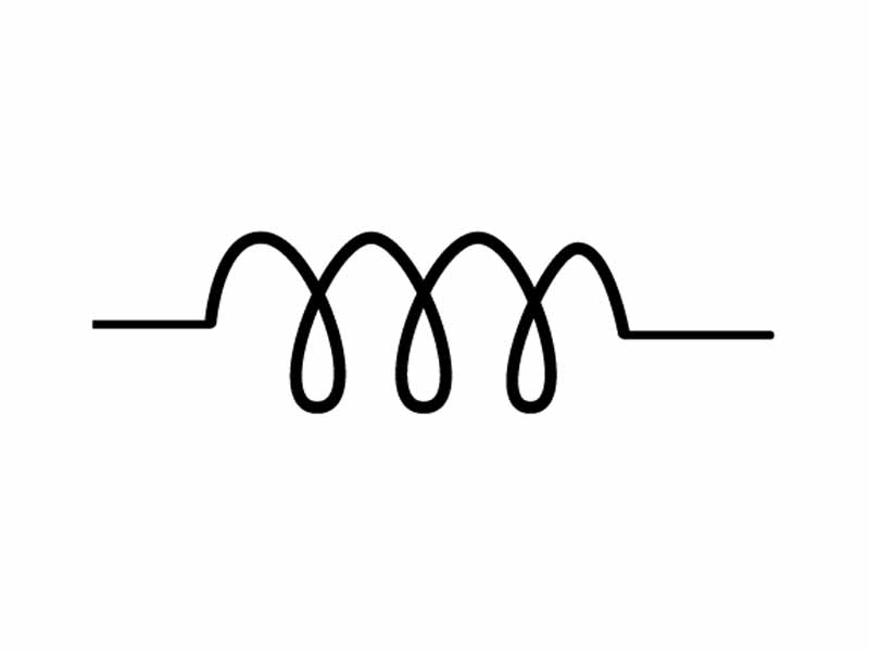
Inductor Symbol. In circuit diagrams, an inductor is represented by a coil or loops. It typically looks like a series of several closely spaced loops or a coil of wire, often with two terminals, as shown below: The ends of the symbol normally indicate the terminals where an inductor can be connected to a circuit.

Inductor Vector SVG Icon SVG Repo
For the calculation by these formulas is enough to know the dimensions of the ring and its permeability. at D1/D2>1.75. at D1/D2<1.75. All dimensions are in millimeters, the inductance in uH. μ is the relative magnetic permeability of the core. In the case of low-current inductors, you can assume it as initial magnetic permeability.

Symbol For Inductor ClipArt Best
We have obtained a solution to this differential equation before (with different variables) - Equation 3.5.8. Following the same procedure to integrate this equation gives the result: (5.4.10)I(t) = E R(1 −e−t τ), τ ≡ LR. Note that the time constant for this circuit is quite different from the one for the RC circuit.

What is Inductor Its Working, Parameters, Factors & Applications
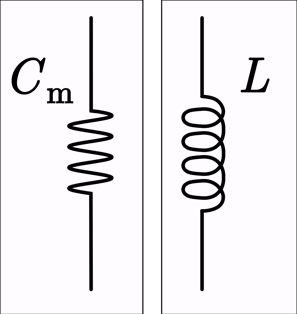
By using Kirchoff's voltage law, the total voltage drop is the sum of the voltage drop across each inductor. That is, V T = V 1 + V 2 +V 3. We know that the voltage across an inductor is given by the equation. V = L di / dt. So, here we can write, L Total dl / dt = L 1 x dl 1 / dt + L 2 x dl 2 / dt + L 3 x dl 3 / dt.