
Light Switch Wiring Diagram Car Anatomy in Diagram
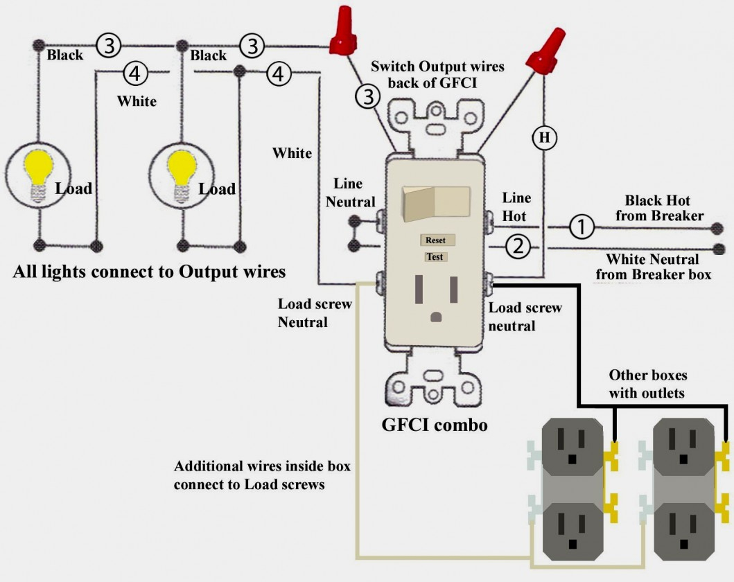
In this simple wiring diagram, the combo switch & outlet is connected to the 120V AC supply through CB. The break away fin tab is intact therefore, line (hot) is connected to the (only) one brass terminal on line side. The neutral is connected to the neutral silver terminal. The switch load brass terminal and neutral is connected to the light bulb.
Wiring Lights And Outlets On Same Circuit Diagram Wiring Diagram
In this video I show how I go about adding a receptacle to any room. No need to cut any holes, add boxes, or run additional wiring. I use a 15-amp tamper r.

Switch Outlet Combo Wiring Diagram A Comprehensive Guide Wiring Diagram
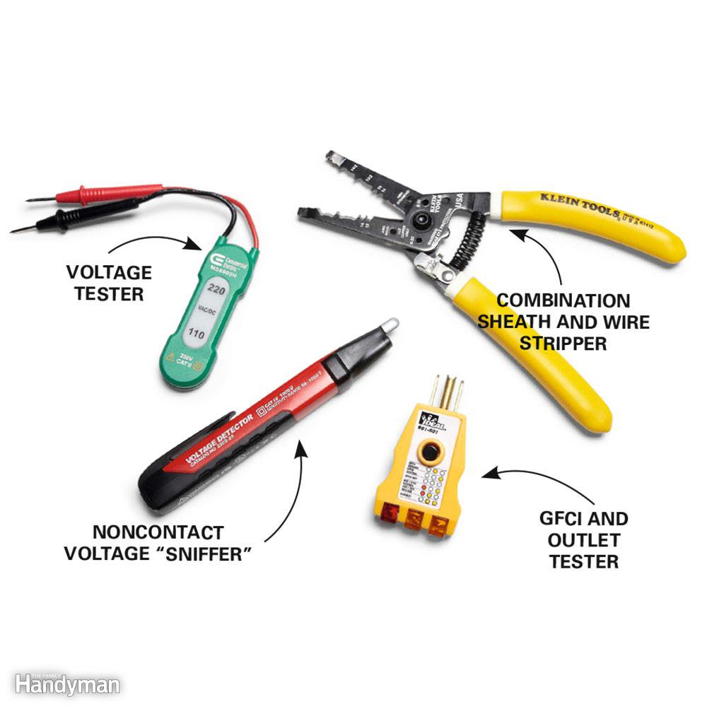
Estimated Cost: $20 Wiring electrical outlets (properly called receptacles) and switches involve many of the same basic techniques. Making safe, long-lasting connections requires properly preparing the circuit wires that will connect to the device and securing each wire to the correct terminal. What You'll Need Equipment / Tools
How To Wire Combination Switch Outlet Switched Outlet Wiring Diagram
Strip the ends of the wires to expose the bare copper and create a loop at the end of each wire using a pair of pliers. This will make it easier to attach them to the device. 3. Install the switch receptacle combo. Next, you will need to install the switch receptacle combo into the electrical box.

Gfci Outlet With Switch Wiring Diagram Wiring Diagram
Switched outlet wiring diagram depicts the electrical power from the circuit breaker panel entering the switched electrical receptacle outlet box where a two-wire cable goes to the switch and another two-wire cable feeds power to another outlet that is live at all times. The wiring diagram above shows how switched outlets are often wired.
Switch Outlet Wiring Diagram Wiring Diagram
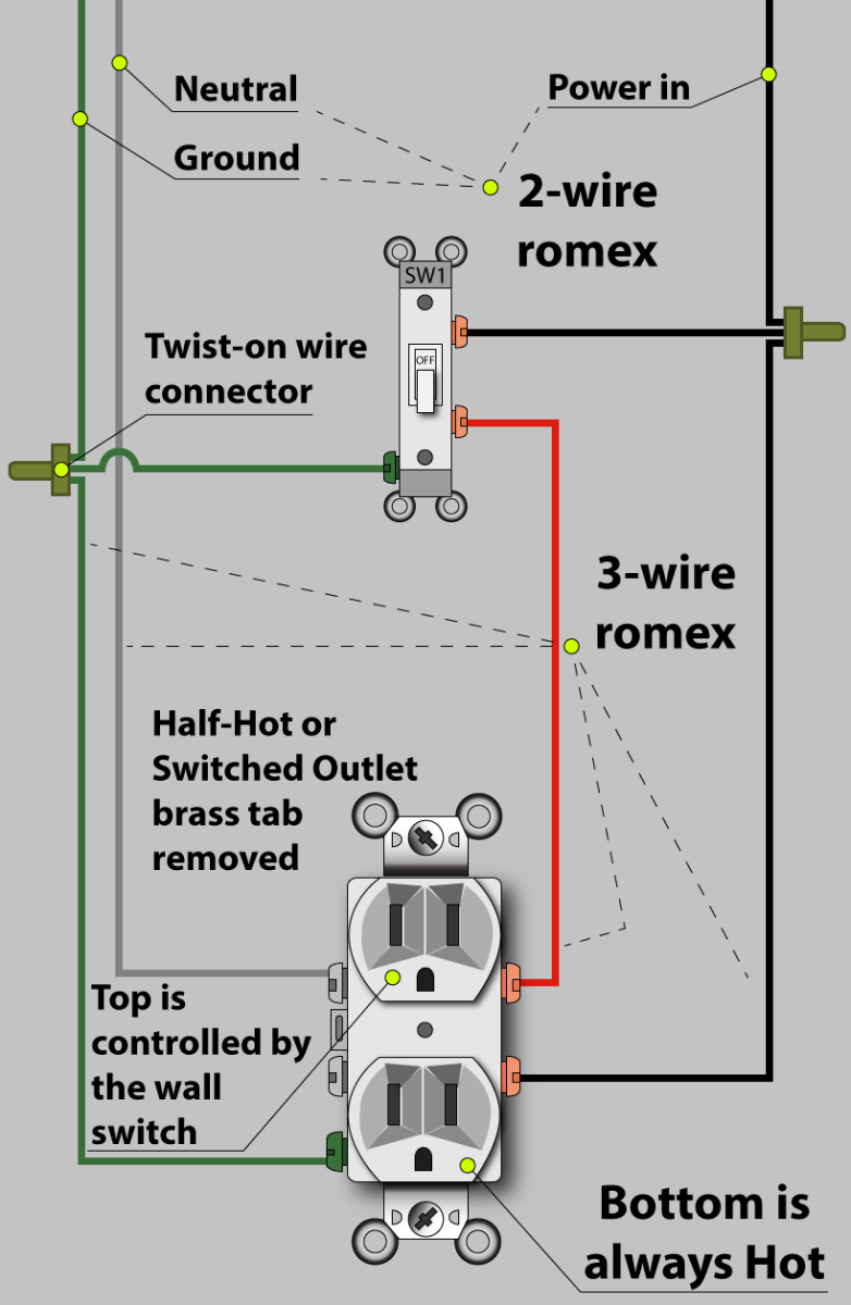
In this diagram, an outlet is added to a 3 way light circuit where the source comes in before the switches. It is not controlled with the switches but is instead always hot. New 2-wire cable runs from the source 3 way switch box to the new outlet location.
Light Switch To Outlet Wiring Diagram Cadician's Blog
This wiring diagram illustrates adding wiring for a light switch to control an existing wall outlet. The source is at the outlet and a switch loop is added to a new switch. The hot source wire is removed from the receptacle and spliced to the red wire running to the switch. The black wire from the switch connects to the hot on the receptacle.

Wiring A Plug To A Switch
A switched outlet diagram is a visual representation of the electrical wiring for a switched outlet. This diagram shows how the electrical current flows from the power source to the outlet and how it can be controlled by a switch. By understanding the wiring diagram, one can easily install or troubleshoot a switched outlet. The switched outlet.
Multiple Outlet Wiring Diagram Cadician's Blog
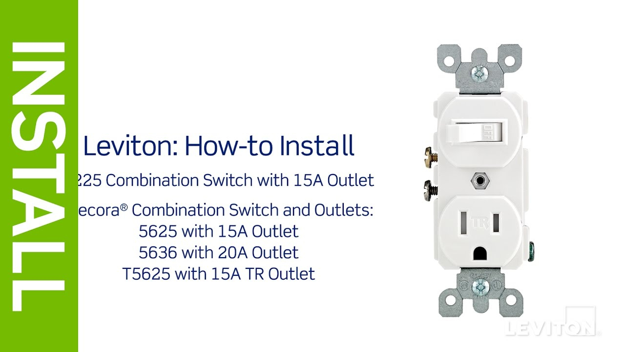
Here is a diagram showing the internal function of the switch/receptacle combination device. Here is an actual picture of a Leviton Switch/Receptacle Combination Device. I will discuss three different possible scenarios where a switch/receptacle combo device such as this would come in handy. Scenario #1

Lights And Outlets On Same Circuit
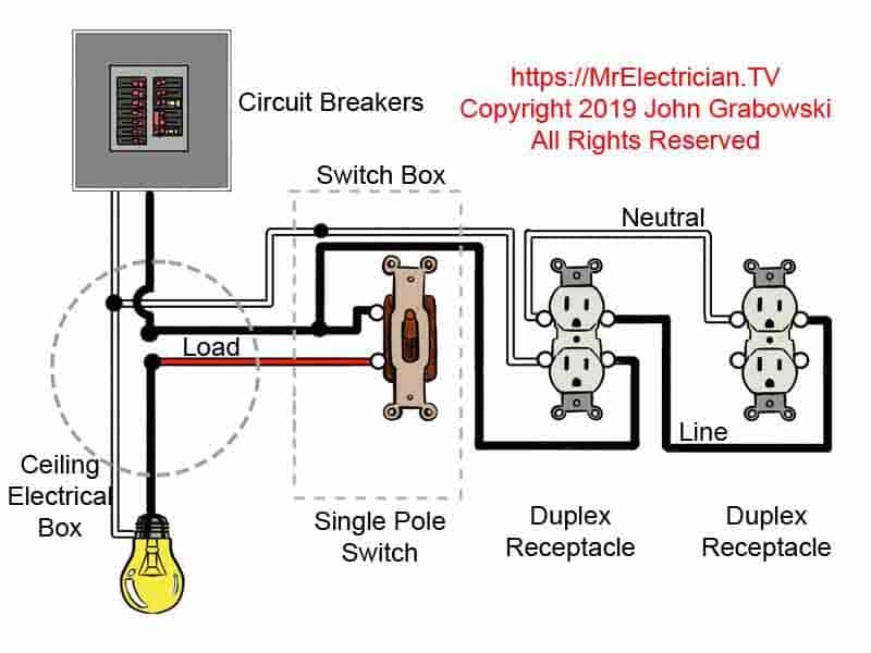
These electrical wiring diagrams show typical connections. The diagram below shows the power entering the circuit at the grounded outlet box location, then sending power up to the switch and a switched leg back down to the outlet.

Outlet Switch Combo Wiring Diagram How To Wire A 3 Way Switch Wiring
Switched Outlet Wiring Diagram. Take a closer look at a switched outlet wiring diagram. You may want to have a plug that has a lamp plugged in and is operated by a switch while keeping the other outlet hot. If that is the case, pick the diagram that is most like the scenario you are in and see if you can wire your outlet.
Light Switch And Outlet Wiring Diagram Database
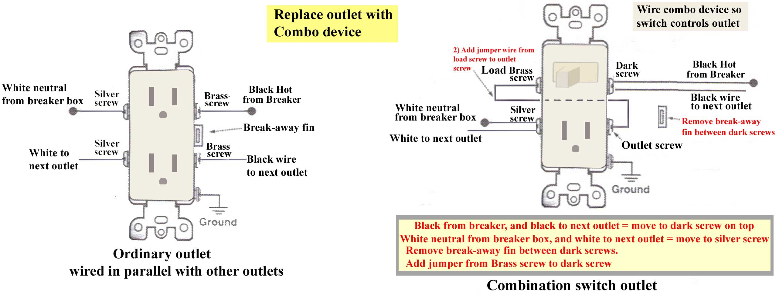
Ground connection diagram is shown separately. Switch controls light only Switch controls light and outlet A metal tab connects the line (right) side of the switch and line side of the outlet. Line is connected to the load side of the switch. The line side of the switch becomes a switched line.

Gfci Outlet With Switch Wiring Diagram Free Wiring Diagram
Author: Terry Peterman Category: Switches & Receptacles, Wiring Diagrams Single Pole Switch to an Outlet Click on Image for Larger How to wire a switched outlet with a single pole switch is illustrated in this wiring diagram.

Wiring Diagram For An Outlet Controlled By A Switch Wiring Diagram
How to read these diagrams. This page contains wiring diagrams for combination switch/receptacle device known as a combo switch. A combo switch is a single-gang device the same size as a standard duplex wall receptacle containing an outlet on one end and a builtin switch on the other.

How To Wire An Outlet To A Switch How To Do Thing
Wiring a Switch and Outlet the Safe and Easy Way | Family Handyman Home House & Components Systems Electrical System Wiring 24 Tips for Wiring Light Switches and Outlets Family Handyman Updated: Dec. 03, 2023 Play it smart and stay safe when wiring outlets and switches Our editors and experts handpick every product we feature.
Wiring A Light Switch And Outlet On Same Circuit Diagram Wiring
Step 1: Gather the Necessary Tools and Equipment Before you begin wiring a Leviton switch outlet combo, it's important to gather all the necessary tools and equipment. Having everything ready will make the process smoother and more efficient. Here are the tools and equipment you will need: A Leviton switch outlet combo