Motor Symbol
times referred to as the motor circuit. Common Control — power and control circuits at same volt-age. Separate Control is at different voltages. The thin lines in Figure 4 represent the control circuit. The magnet coil of the starter is energized with this circuit, which creates the electro-magnetic field that pulls the power circuit.

Motor schematic diagram Download Scientific Diagram
Synchronous Electric Motor Symbols. Synchronous motors are a type of alternating current motor in which the rotation of the axis is synchronized with the frequency of the supply current; the rotation period is exactly equal to a whole number of AC cycles. It may interest you. Electric motors Three-phase motors Download symbols + Info.
Electric Motor Icon And Symbol Stock Illustration Illustration of
19 Schematic vs. Wiring Diagrams One of the most frequently used diagrams in motor control work is the ladder diagram, also known as a schematic diagram. This diagrams uses symbols to identify components and interconnecting lines to display the electrical continuity of a circuit. Ladder diagrams show how a circuit works logically and electrically.

house switch wiring
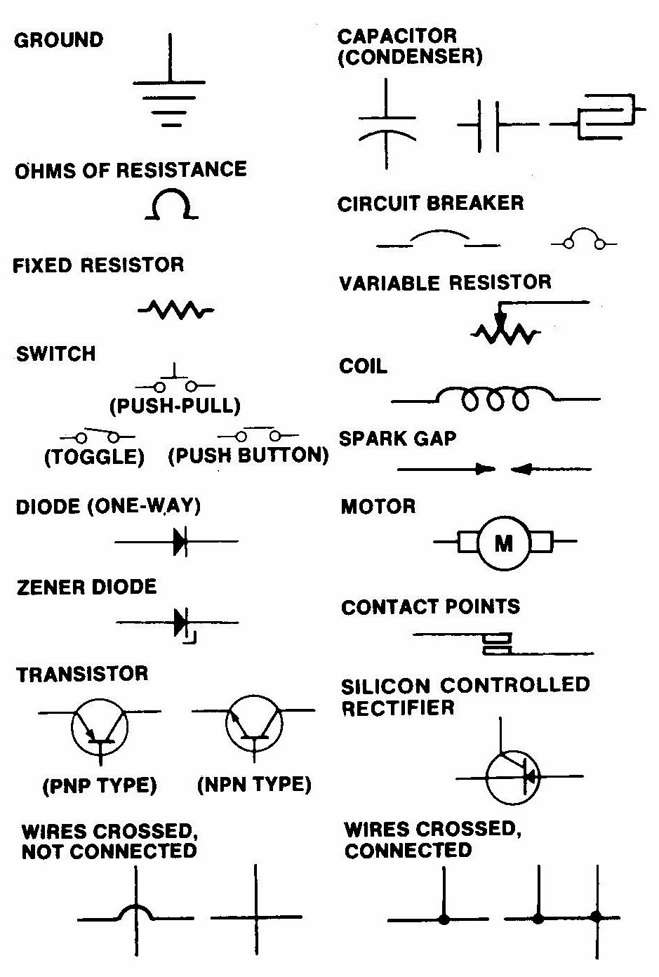
Electrical & electronic symbols and images are used by engineers in circuit diagrams and schematics to show how a circuits components are connected together. Circuit layouts and schematic diagrams are a simple and effective way of showing pictorially the electrical connections, components and operation of a particular electrical circuit or system.

Electrical Wiring Diagram Symbols Pdf Electrical engineering projects
Electric Motor Symbols [ Go to Website ] 1/2 All Electrical & Electronic Symbols in https://www.electrical-symbols.com. electronic components; electronic design; electronic circuits; digital electronics; schematic; ANSI; NEMA; IEEE; IEC Created Date: 9/20/2019 5:38:56 PM.

Schematic Symbols — cip learning store
Capacitor Symbols; Capacitor: Capacitor is used to store electric charge. It acts as short circuit with AC and open circuit with DC. Capacitor: Polarized Capacitor: Electrolytic capacitor: Polarized Capacitor: Electrolytic capacitor: Variable Capacitor: Adjustable capacitance: Inductor / Coil Symbols; Inductor: Coil / solenoid that generates.

Electric Motors Symbols AC/DC, Single Phase / Three Phase Motors
It is the symbol used for DC shunt motor whose field winding is connected in parallel to the armature winding. Both windings are connected to a common Direct Current supply. Single Phase Synchronous Motor. This symbol represents a single phase AC synchronous motor. Synchronous motors initially starts as an induction motor but later achieves a.
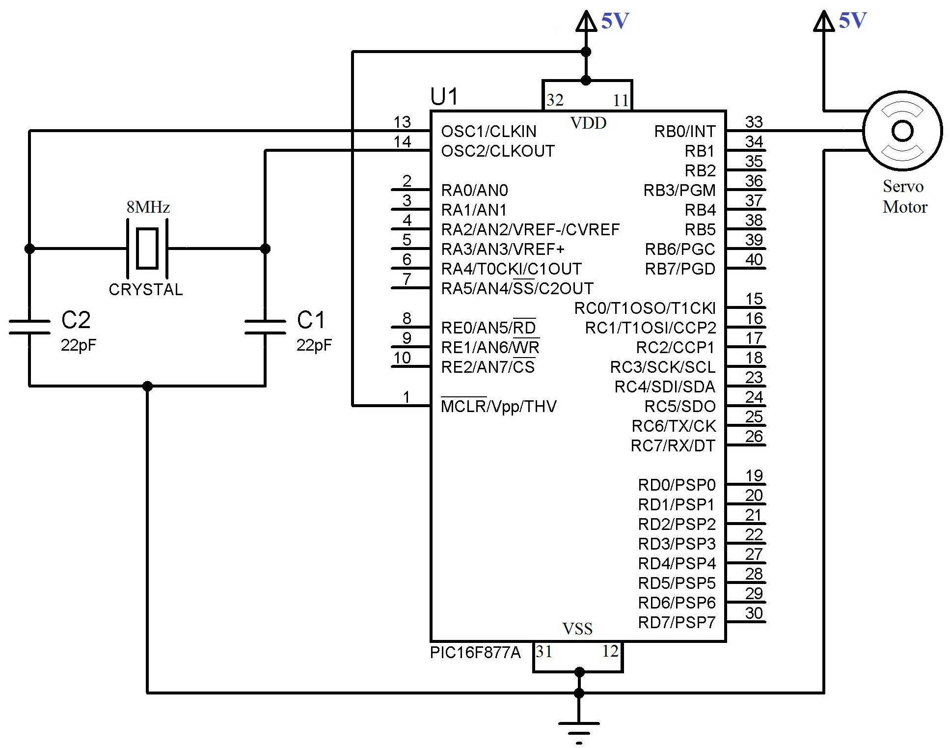
Servo Motor Schematic Symbol Wiring Diagram Schemas
The schematic diagram of an electric motor typically includes components such as a rotor, stator, commutator, brushes, and a power supply. These components work together to generate rotational motion. The rotor is the rotating part of the motor, while the stator is the stationary part. The commutator and brushes serve as the electrical.
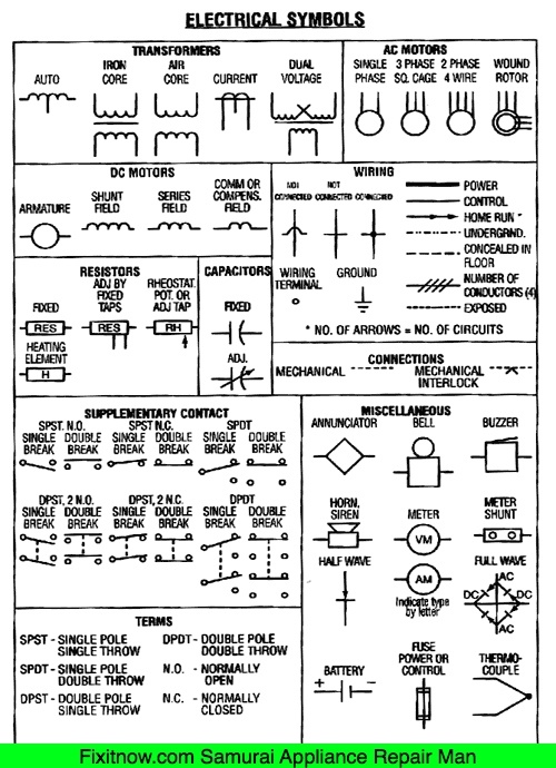
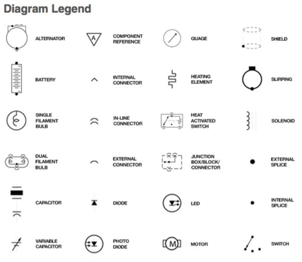
Electrical Symbols on Wiring and Schematic Diagrams
symbols will lead to a quicker understanding of each circuit. The symbols, device designations, and abbreviations in this book are taken from the NEMA Standard Publication/No. ICS-1-1978. Wiring Diagram Symbols Device Symbol Fuse General Single Winding I Relay Tapped and Switch Coils Coils NE - Neon FL - Fluorescent --@I-
Fundamentals to understanding automobile electrical and vacuum diagrams
Electrical Symbols and Line Diagrams Chapter 3 Material taken from Chapter 3 of Electric Motor Controls, G. Rockis, 2001 One-Line Diagrams One-line diagram - a diagram that uses single lines and graphic symbols to indicate the path and components of an electrical circuit. One-line diagrams are used when information about a circuit is required
Antenna Rotor Part 1 Lets Hack It
Electric Motor Symbols. Electric motors are electromechanical devices whose function is to transform electrical energy into mechanical energy through electromagnetic interactions. There are other engines ( generators) that produce electricity by exploiting the mechanical energy, such as alternators and dynamos.
Motor Circuit Symbol
Circuit Symbols The following are the circuit symbols commonly used in motor related schematic diagrams. Panel Wiring Techniques Electrical control panels are available in all shapes and sizes to suit the particular requirements of the situation. These panels may be small as shown in Figure 2, or very large as required to house the necessary.

MOTOR SYMBOL AutoCAD Free CAD Block Symbols And CAD Drawing
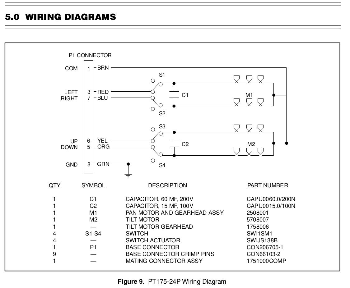
Wiring diagrams show the connections to the controller. Wiring diagrams, sometimes called " main " or " construction " diagrams, show the actual connection points for the wires to the components and terminals of the controller. Basic wiring for motor control - Technical data. They show the relative location of the components.
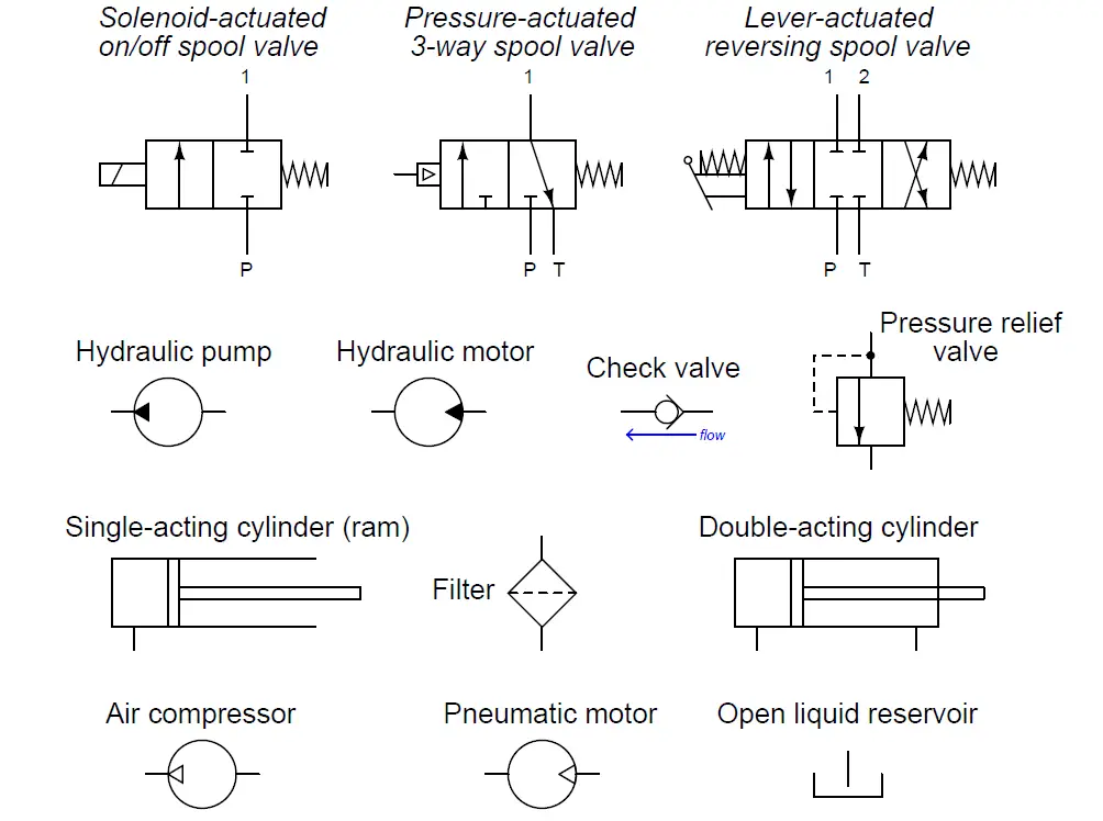
Fluid Power Systems Hydraulic System Working Instrumentation Tools
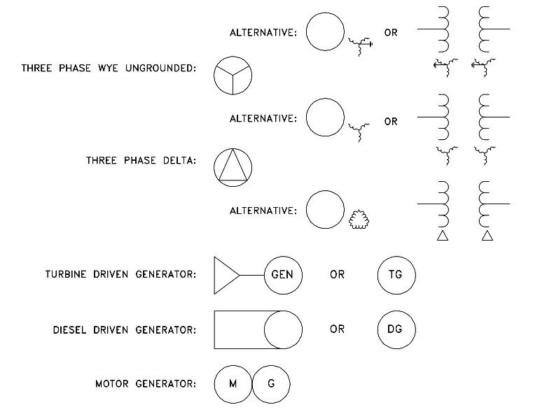
all symbols > electrical installations > machines > motors. replusion motor, 1 phase EN 6061706-06-02. series motor, 1 phase EN. DC EN 6061706-05-02. shunt motor, DC EN 6061706-05-01. linear induction motor, 3 phase, movement only in one direction EN 6061706-08-05. induction motor, 3 phase, with wound rotor EN 6061706-08-03. induction motor.
Motor Schematic Symbol
A DC motor schematic symbol is a graphical representation of a direct current motor in an electrical circuit diagram. It is used to indicate the presence and function of a DC motor in a system. The DC motor schematic symbol typically consists of a circle with a letter "M" inside, representing the motor itself..
electric motor symbol wiring diagram
A distinction is drawn between: All about wiring of electric motors (photo credit: electronics.stackexchange.com) Block diagram - Simplified representation of a circuit with its main parts. It shows how the electrical installation works and how it is subdivided. Circuit diagram - Detailed representation of a circuit with its individual.