What is MCCB? Functions, Components and Applications of MCCB.
Circuit diagrams are essential components of any electrical system, and Metal-Clad Switchgear (MCCB) circuit diagrams are no different. In particular, MCCBs are used in high-voltage systems to provide protection from over-currents and short circuits.

How To Make MCCB Simple Diagram MCCB YouTube
The MCCB circuit diagram is typically divided into two parts: the operating part and the protection part. The operating part is responsible for controlling the current flow, while the protection part helps to prevent damage to the electrical system. The operating part of the MCCB circuit diagram contains several components.

10+ mcb block diagram Bynanikpriyono
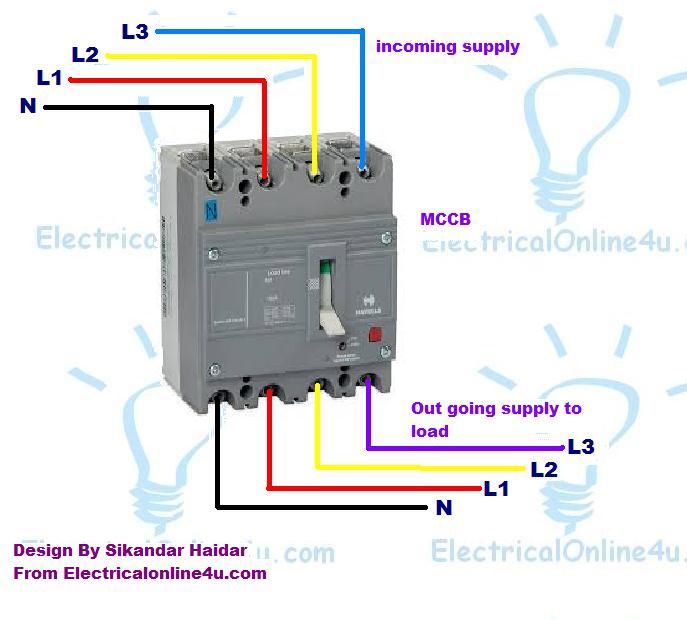
The circuit diagram for an MCCB can vary depending on the type of trip unit used, but generally it consists of a supply line, a load line, and a ground line. The trip unit is connected between the supply line and the load line, and will monitor the current flowing through the circuit.

Schneider Mccb Wiring Diagram Wiring Diagram
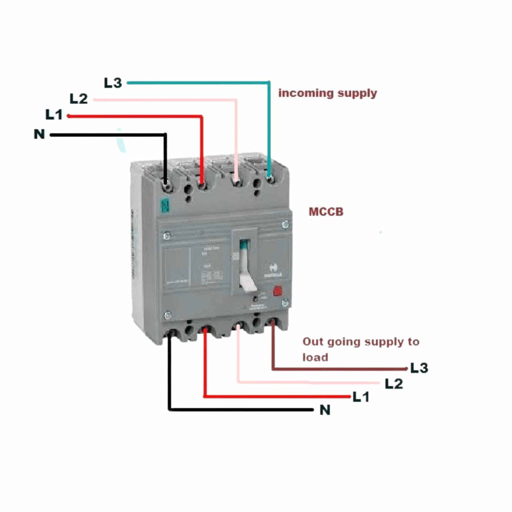
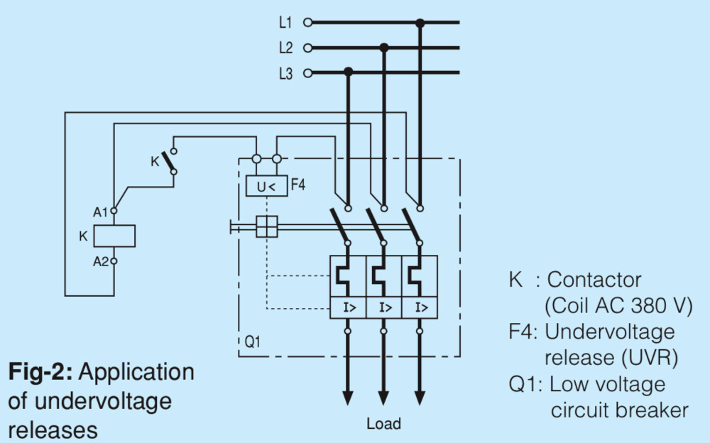
2- MCCB Connection Diagram: 3- Working principle of MCCB: MCCB is an electromechanical protection device on the range of 100A to 1600A, which protests the electrical circuit from over current, short circuit and earth fault. Mainly two function are used MCCB as overload and short circut. Earth fault are also used for additional.
Dismantle MCCB/ELCB/ RCCB and Identification of Various Parts Free Electrical Notebook
At its core, an MCCB (Molded Case Circuit Breaker) wiring diagram is a visual representation of the various components and connections of an electrical system. It includes all the necessary information to understand how power flows through the system and how different components are interconnected. These diagrams use symbols and codes to.
3 Pole Circuit Breaker Wiring Diagram MCB Connection Voltage Lab
Starting with the basics, an MCCB circuit diagram consists of two primary elements: a battery and a breaker. The battery supplies power to the breaker, which in turn regulates the flow of current throughout the electrical system. In other words, the MCCB circuit diagram shows how the energy is distributed in the system.
Motorized Mccb Wiring Diagram Creativeal
At its core, an Mccb circuit diagram is a map that shows the connections between various components in an electrical circuit. Mccb stands for "molded case circuit breaker," which is a type of circuit breaker that protects against overcurrent and short circuits.

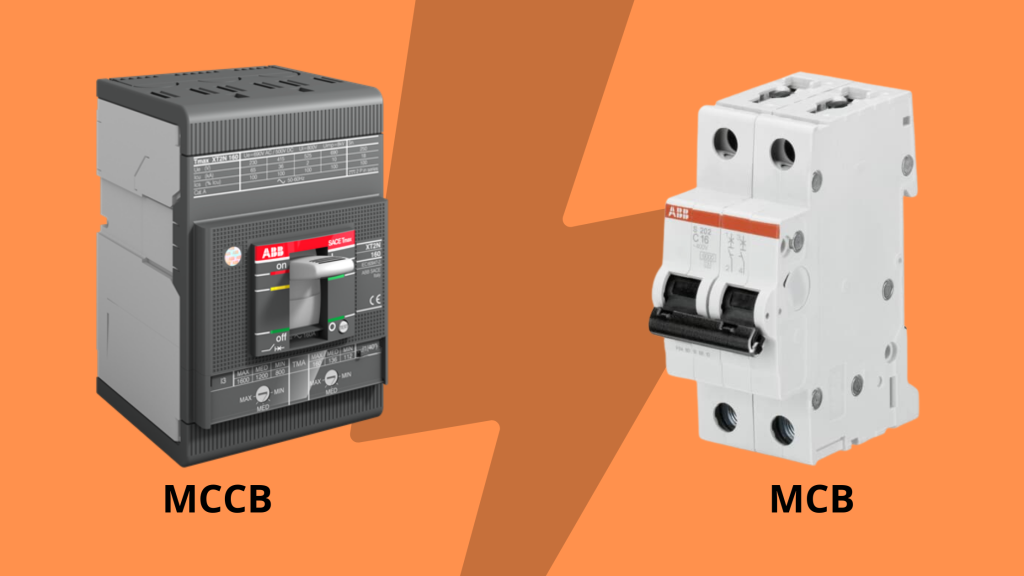
MCCB Full Form MCB and MCCB Difference ETechnoG
A molded case circuit breaker, or MCCB, is a safety device used to protect an electrical circuit from overload or short circuits. It works by automatically cutting off the power supply when a fault or overcurrent situation arises, thus preventing any damage to the electrical system. MCCBs can be used in both low-voltage and high-voltage systems.
Motorized Mccb Wiring Diagram Creativeal
MCB Circuit Diagram It is also defined as the electromechanical device that guards an electrical circuit against an overcurrent, that may affect by a short circuit, overload, or imperfect design. This is a better option to a Fuse since it doesn't require alternate once an overload is identified.
MCCB Molded Case Circuit Breaker Working Principle Ratings
June 30, 2020 by mariaelectricals. A molded case circuit breaker (MCCB) is a type of breaker used to protects electrical circuits from overcurrents arising from overload, short circuits, or faulty wiring. It is like a miniature circuit breaker (MCB), however, MCCB has higher features. Molded case circuit breakers have a higher current rating of.
Motorized Mccb Wiring Diagram
A MCCB circuit diagram is basically a schematic of how the device is connected to the other elements of a circuit. It usually includes a pictorial representation of the different components and their connections, as well as their relevant electrical symbols.

Proper RCCB connection Diagram with MCB ETechnoG
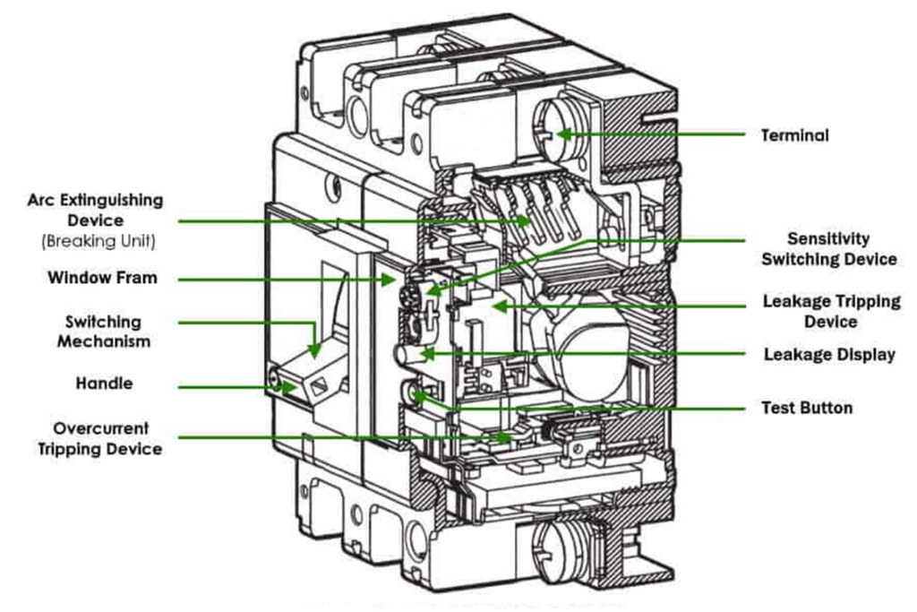
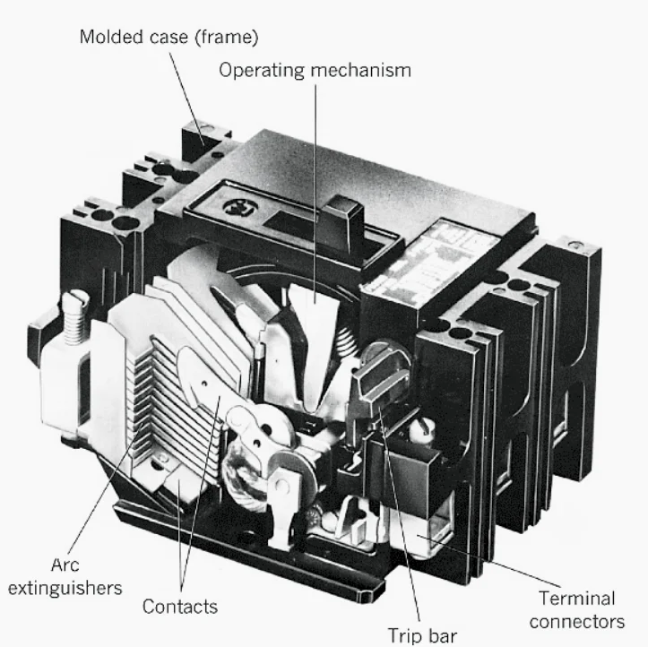
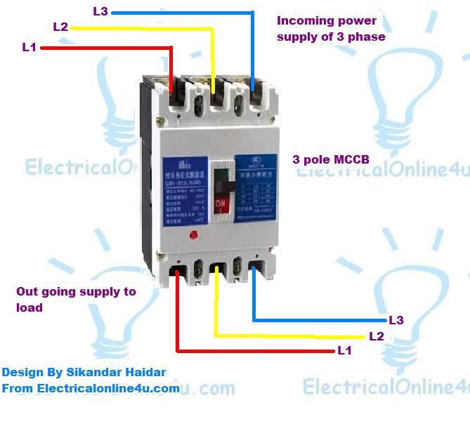
Single Line Diagram The input and output of the moulded case circuit will be bottom and top side. Construction: MCCB Consists of 9 different parts such Arc chute Moving Contact Operating mechanism Base cover Terminal Connector Overload trip or Bimetallic contact Handle knob Manual trip button CT - Current Transformer assembly

MCCB (Molded case circuit breaker) Parts and Functions
Comparison Chart Miniature Circuit Breaker (MCB) The miniature circuit breaker is an electromechanical device which, automatically, switch off the circuit whenever the abnormal condition occurs. It easily senses the overcurrent caused by the short circuit. The working principle of the miniature circuit is very simple.

Schneider Mccb Wiring Diagram Wiring Diagram and Schematic
MCCB (full form: moulded case circuit breaker) is used for 250 amps to 800 amps in the motor feeders. This system of circuit breaker basically protects the entire electrical system from overloading and having such conditions of short circuit issues. To simply put it these are the electrical protection gadgets that are used mostly with a wide.
How does a Molded Case Circuit Breaker Work?
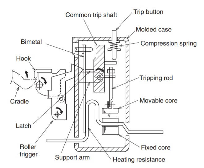
A molded case circuit breaker (MCCB) is a circuit breaker that uses a molded case to house and supports its current-carrying components as well as to be a part of the insulation system. The working principle of MCCB is discussed in detail in this article. The most common type of MCCB is the thermal-magnetic general-purpose circuit breaker.
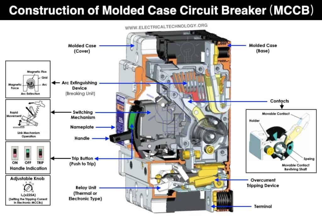
MCCB (Molded Case Circuit Breaker) Construction, Types & Working
An MCCB has many internal and external components. Each component is important, but the MCCB must be able to interrupt the circuit. MCCB (Molded case circuit breaker) Parts. MCCB (Molded case circuit breaker) can be operated easily and have excellent switching performance and breaking performance. The major components of an MCCB are the.