Prestige Induction Cooker Service Manual
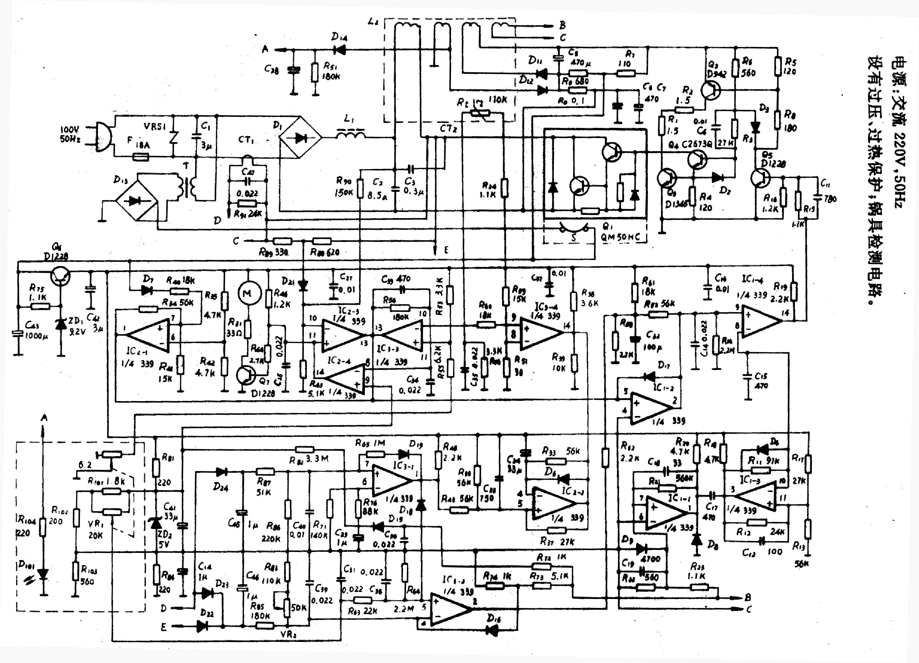
Block Diagram of C2000 Dual VF Resonant Induction Cookers The main power supply is obtained directly from the grid or AC source, 220VAC 50 Hz. The auxiliary power supply provides energy to fan, IGBT driver, detection circuits, and MCU.
Top 78 + Induction stove working principle animation
By Clint Byrd | December 25, 2017 0 Comment Induction cookers are rapidly gaining in popularity, as they provide a more energy efficient and safe way to cook compared to traditional stovetops.

☑ Induction Heating Circuit Using Igbt
Induction cookers have become a popular choice for many in recent years. Induction cookers provide a more efficient and cost-effective way to cook, while being much safer than traditional gas or electric ranges. Understanding how induction cookers work and correctly wiring the circuit is essential for safe and effective use.When it comes to understanding induction cooker circuit diagrams.

Induction Stove Circuit Diagram Download
complete induction cooker as a quick start reference design for customers. This application is an implementation example of System Design Guideline for 5V 8-bit families in Home Appliance Applications (AN4476) and How To Develop a Robust Software in Noise Environment (AN4463). Contents

Induction Cooktop Circuit Diagram Wiring Digital and Schematic
in this video i explained working principle of #Induction #Cooker #Heater Functional & Circuit diagram Description, Repair Troubleshooting, after watching th.

Monogram Induction Outlet Store, Save 51 jlcatj.gob.mx
The efficiency of the AC based existing induction cooker was measured and found to be 85.56%. The functional circuit diagram of the existing induction cooker was simulated in Multisim and efficiency was calculated to be 87%. A solar electricity based DC induction cooker using quasi resonant topology has been designed and simulated.
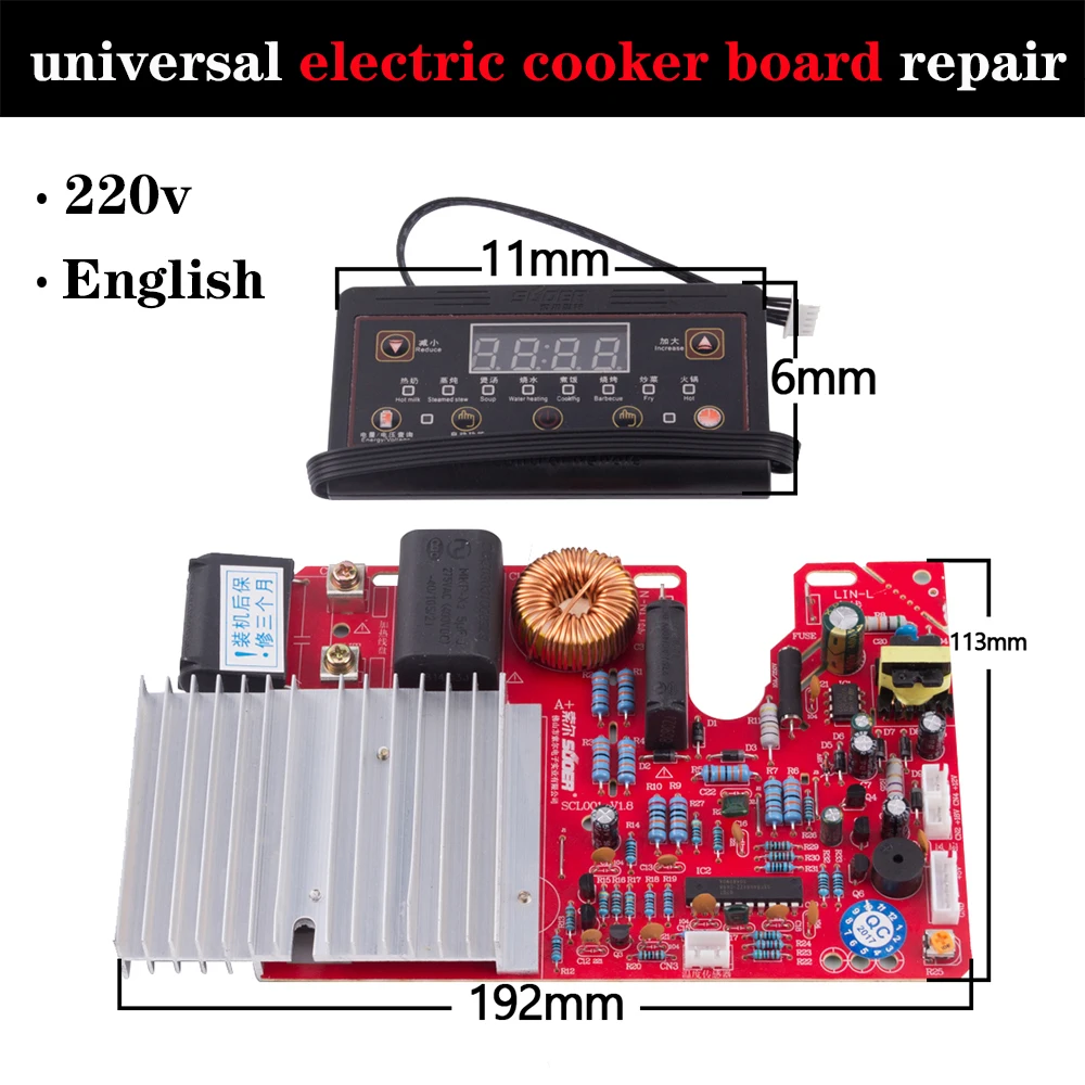
UniversalInductionCookerModifiedBoardRepairElectricStoveSparePartsCircuitDiagram
An induction cooker schematic diagram typically shows the coils, magnets, and other components that make up the cooktop. It also includes diagrams of the control panel, power supply unit, and wiring diagrams that are used to control the power supply and heat output of the induction cooker. The diagram also includes detailed information about.

123 Induction cooker Schematics Protel Schematic Guang Dong Xinbao Electrical Appliances Holdings
This video explain the physics, circuit and firmware design of commercial induction cookers. Ampere's Law, Maxwell Faraday Equation, eddy current, Lenz law a.

Schematic Circuit Diagram Of Induction Cooker Wiring Diagram
The induction cooktop's circuit diagram helps explain how it works. At the heart of the diagram is the induction coil, which is composed of two components - a primary coil and secondary coil. The primary coil is connected to the electrical power source, while the secondary coil is wrapped around the cooking vessel.
Cooker Circuit Diagram
Induction Cooker Circuit Diagram December 14, 2022 by Ana Oshi Induction cookers are a revolutionary form of cooking technology that has revolutionized the professional and home kitchen due to its energy efficiency, safety, and convenience.

Prestige Induction Cooker Circuit Diagram Pdf Converter Zoya Circuit
We have specifically developed trench-gate field-stop IGBTs and diodes that, together with a selection of high-voltage gate drivers and high-performance STM32 microcontrollers, are ideal for use in high-efficiency converters. ST also offers environmental sensors and the LED and LCD display drivers, touchscreen controllers and proximity and.

Induction Cooker Microcontroller Circuit Diagram
INDUCTION COOKERS REPAIR GUIDE; If you have any question about repairing write your question to the Message board. For this no need registration. If the site has helped you and you also want to help others, please Upload a manual, circuit diagram or eeprom that is not yet available on the site. Have a nice Day! See related repair forum topics.
[DIAGRAM] Schematic Circuit Diagram Of Induction Cooker
2007-11-10 10:52:30. Document Title. Protel Schematic. Document Creator. pdfFactory Pro www.fineprint.cn. Document Author: K500031. Induction cooker schematics details for FCC ID VIU123 made by Guang Dong Xinbao Electrical Appliances Holdings Co., Ltd. Document Includes Schematics Protel Schematic.

12+ Induction Cooker Circuit Diagram Robhosking Diagram
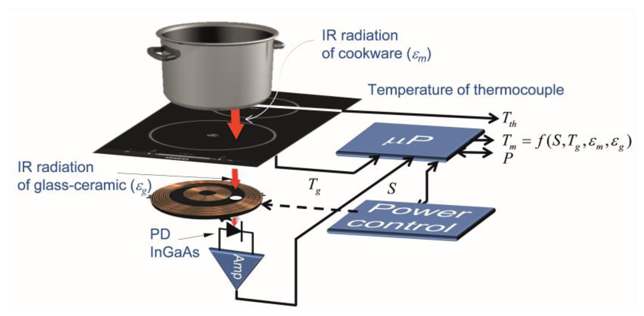
cooker with a schematic diagram on the left. Induction stoves are normally equipped with more than one induction cooking plate. Figure 1: Induction cooker plus schematic diagram. Induction cooking has several advantages over traditional methods of cooking: • speed: the heat transferred to the food is very direct because the cookware is heated.
laptop diagram Circuit Layout Induction Cooker Schematic Circuit Diagram
Context 1. mechanism of heat on ferromagnetic-based cooking equipment can occur due to the emergence of eddy currents at the base of the cooking equipment. In summary, the working principle of.

Dc Induction Cooker 24V Circuit Diagram 12v Induction Heater Circuit Diagram Limited time
I am new to electronics So I need help to understand the working of the induction cooker circuit. I searched on the google but could not find the simple answer. Below is the attached circuit commonly found in home based induction stoves but it seems to be totally different from the theoratical circuit on the internet.